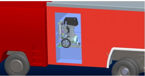
ZS-CAFS60-EVO9 compressed air foam system
Product manual
I. Product Overview
The ZS-CAFS60-EVO9 compressed air foam system developed by Shanghai Zishu Industrial
Co., Ltd. is suitable for various fire vehicle chassis and fire pump. It can not only be flexibly
applied to all kinds of compressed air foam fire engines, but also can be used to upgrade
existing water tank (foam) fire engines, and can also be used to integrate fixed compressed
air foam systems.
This product has high integration, safety and reliability, good adaptability, flexible
installation, and easy use.
II. Product composition and performance parameters
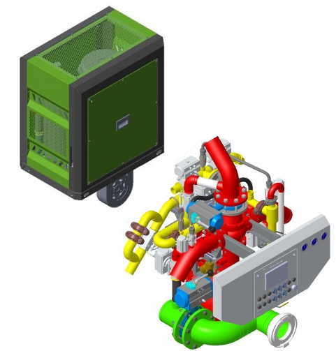
The system mainly includes compressed air module, pump pipeline and foam proportion
control system.
1. Compressed air module
It mainly consists of components such as air compressor, air filter, intake control valve, oil�
gas separation device, cooler, and transmission device, as shown in the following figure:

Note: the pictures are for reference only, and the actual product configuration
is subject to the purchase contract.
Main parameters:
➢ Air compressor:
Rated air flow rate: ≥ 5040L/min
Rated air pressure: 1.0MPa
Maximum air pressure: 1.5MPa
Rated power: 39kW
➢ Intake control valve:
The intake control valve can control the pressure of compressed air in real
time to maintain balance with the water pressure of the fire pump.
2Product manual
➢ Oil and gas separation device:
The oil and gas separation device includes an oil and gas separation drum
(and an oil and gas fine separator) to ensure that the output air meets the
system requirements.
➢ Transmission:
The transmission device drives the air compressor through the power take�
off to meet the compressed air demand of the CAFS system.
2. Pump pipeline and foam proportion control system
Pump pipeline and foam proportional control system are composed of fire pump,
foam pump, pipeline (water inlet and outlet, foam, air) and control panel, as shown in
the figure below:

Note: the pictures are for reference only, and the actual product configuration
is subject to the purchase contract.
The working principle of foam proportion control system is:
The self-developed controller is used to collect the outlet flow of the fire pump in real time.
By controlling the outlet flow of the foam pump (metering plunger pump), the required
foam stock solution is accurately injected into the outlet pipeline, so as to ensure that the
foam proportion can be kept at the set proportion under any water flow.
The control of foam proportion is fully automatic and electronic, without manual
adjustment.
The liquid outlet pipeline is equipped with dry and wet foam switching device.

Note: that this control schematic is for reference only. Components such as
fire pumps and fire monitors may not be included in the provided product.
The actual product configuration is subject to the purchase contract.
Main parameters:
➢ Fire pump performance parameters:
➢ Rated flow rate: 60L/s
➢ Rated pressure: 1.0MPa
➢ Performance parameters of foam plunger pump:
➢ Rated flow: Recommended 9L/ min@1.0MPa (Other traffic options available)
➢ Rated pressure: ≥ 1.0MPa
5Product manual
➢ Voltage: DC24V (optional DC12V)
➢ Foam ratio: 0.2~1.0% stepless adjustable
➢ Control mode: fully automatic electronic adjustment
III. Product installation
1. Compressed air module: Refer to the following diagram for the appearance and
installation dimensions of the compressed air module:
Outline and installation dimension diagram of compressed air module
Note: the appearance and installation dimensions are for reference only.
Please refer to the installatio
n diagram provided in the technical agreement
attached to the purchase contract for details.
2. Pump pipeline and foam proportion control system
➢ Refer to the figure below for the outline and installation dimensions of pump
pipeline and foam proportional control system:

Outline and installation dimensions of pump pipeline and foam proportional
control system
Note: the appearance and installation dimensions are for reference only.
Please refer to the installation diagram provided in the technical agreement
attached to the purchase contract for details.
7
Hot Tags:


